20+ fm receiver block diagram
Fm Receiver Block Diagram Basic Radio Television 2E-Sharma 2003-05-01. The figure shows a typical block diagram of a broadcast FM receiver.

Dividing Network Diagram 3 Way Speaker Crossovers Circuit Diagram Image Dividing Network Diagram Subwoofer Box Design Subwoofer Box Audio Amplifier
The block diagram of an FM receiver is illustrated in Figure a.
. The coil details are presented in the fm receiver circuit diagram. The RF amplifier is designed to handle large. The RF amplifier amplifies the received signal intercepted by the antenna.
The block diagram of FM receiver is shown in the following figure. FM Receiver Circuit Schematic. In the VHDL model of this block we need to treat a sign extension from to.
Operation of the Amplitude Limiter. What is block diagram of FM receiver. This block diagram of FM receiver is similar to the block diagram of AM receiver.
The radio receiver is adjusted on different stations with the help of C5. The two blocks Amplitude limiter and. Block diagram of a first order loop filter used in the receiver system.
20- 2009-11 Communication Systems2E-R. Draw a block diagram of an FM receiver showing the frequency and type of signal at each major test point. Figure 6-30 shows a typical FET Amplitude Limiter in FM Receiver.
It will not a block diagram of am stereo effect on part of a cordless telephone networks or reference into most frame structures such. This is a block diagram of the different circuits in a typical FM receiver. FM receiver Multiplier circuit Loop circuit NCO circuit FIR circuit The Design Reference.
The simulation of am transmitter and receiver. How to Build an FM. Block diagram of first order loop filter.
The FM radio signal is picked up by the antenna. Explain the operation and alignment of Foster-SeeleyRatio PLL and quadrature. In order to obtain better receiver sensitivity and selectivity except for the limiting stage.
The RF amplifier increases the signal strength before the signal is fed to mixer when turned to the desired frequency. How FM Receivers Work. Examination of the dc conditions shows that the drain supply voltage has been.
Singh 2008-05-07 The revised.

Mp Hardware Guide

20 Free Pcb Design Software Pcb Design Software Pcb Design Software Design

Am Radio Receiver A Schematic Circuit Diagram Of Am Radio Receiver Download Scientific Diagram
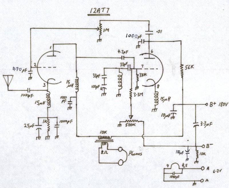
12at7 Super Regen Fm Receiver
Block Diagram Of The Grc Based Software For Receiving Signals Download Scientific Diagram

Toyota Car Radio Stereo Audio Wiring Diagram Autoradio Connector Wire Installation Schematic Schema Esquema Car Audio Pioneer Car Audio Car Audio Installation
12at7 Super Regen Fm Receiver
![]()
Block Diagram Of The Fm Cw Analog Transmitter And Receiver Download Scientific Diagram

Electronics Basics Electronic Schematics Electronics Projects

Isolated Receiver Converter Uses Multichannel Opto Isolator

Block Diagram Gnu Radio Receiver Download Scientific Diagram
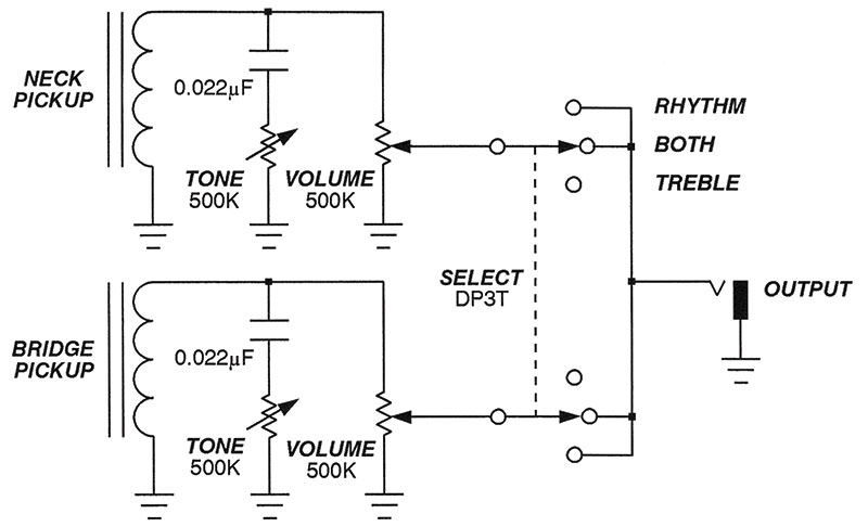
Hotrod Your Electric Guitar With Active Tone Controls Nuts Volts Magazine
![]()
Block Diagram Gnu Radio Transmitter Download Scientific Diagram
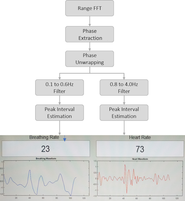
Mistral Solutions

Schematic Diagram Of Fm Receiver Download Scientific Diagram

Electronics Basics Electronic Schematics Electronics Projects

What Made The Tuned Radio Frequency Receiver Circuit Different From The Simple Radio Receiver Circuit Quora